Contact Us
SaleTel:
Tel:
Fax:

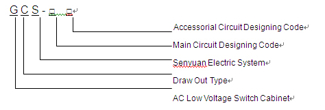
GCS Low Voltage Draw-out Switchgear Cabinet
GCS Low Voltage Draw-out Switchgear Cabinet accords with the requirements to standards of GB7251.1, JB/T9661 and IEC439-1, adapted to electric systems with rated voltage of 380-660V, AC 3-phase 50-60Hz, for power distribution and electromotor controlling and no-power compensation. The product can be designed as drawer type or fixed type system, for indoor use.
◆ The ambient temperature should be not higher than +40℃, not lower than -5℃. The average temperature during 24 hours should be not higher than +35℃;
◆ Latitude should not be over 2000m;
◆ The around air relative humidity should be not more than 50% when the highest temperature is +40℃. The relative high humidity is allowed in lower temperature. (For example, 90% when +20℃);
◆ Gradient between the equipment and vertical side should be no higher than 5°during installation;
◆ Cabinet should be installed at sites with no fierce shaking and impacts, and at places to avoid electric component from erodent.
◆ Users can negotiate with the manufacturer when they have special requirements.
3.4 Bus Transition Switch
4.3 The moving and heating stabilities of the horizontal bus are perfect to support impact by 80/176kA short circuit current.
4.4 Considering the requirements to automatic electric sets in power plant with high capacity, petrochemical and other industries, the maximum amount of loops in single MCC cabinet is 22.
4.5 The connection between equipment and outer cable is completed in the cable partition shelf. Cables can be put in and out through upper or lower holes. Null current mutual inductor is installed in the cable shelf for easy maintenance and installation.
4.7 There are enough second junction plug-ins in drawer unit, (One unit – 40 pairs, half unit – 20 pairs), to satisfy the requirements to amount of junction points of interface of computer and self-controlling loop.
5 Function Units
5.5 ZJ-2 type commutator is adapted for connecting 1/2 unit drawer and cable self.
5.6 Same sized stick shape or pipe shape ZJ-1 type commutator is adapted to connect he unit drawer and cable shelf differed by current.
5.7 There are clear marks of closing, opening, testing and drawing on the interface of the drawer.
1 Characteristic
1.1 8MF type steel is used to make main structure of the equipment. Two structure styles are adopted to make the structure, junction and partly jointing. There are module hole for installing. E=20
1.2 Every function unit of the equipment is divided strictly. The units are mainly function cell unit, bus bar unit and cable unit. Function of each unit is relatively separated.
1.3 Dimension of the cabinet is as follows,
|
Height
|
2200
|
|||||||||
|
Width
|
400
|
600
|
800
|
1100
|
||||||
|
Depth
|
800
|
1000
|
800
|
1000
|
600
|
800
|
1000
|
600
|
800
|
1000
|
1.4 Considering the universal use and security of the dry-type transformer and the economy of the oil immersed type transformer, the equipment can be grouped with dry-type transformer conveniently, or easily connected with low voltage bus bar of the oil immersed type transformer.
2 Cabinet Structure
2.1 PC Cabinet
PC cabinet is general power cabinet, contacting cabinet and reactive cabinet.
2.2 MCC Cabinet
As a function unit of operating the electromotor cable, MCC cabinet is designed into various types by width, depth and different junction methods of branch loop.
2.3 Capacitor Non-power Compensation Cabinet
For Capacitor non-power compensation cabinet, please refer to main loop circuit project No. 33, No. 34. The structure is basically same as it of the power-receiving cabinet.
3 Bus Bar System
To improve the heat stability of the bus bar and temperature’s uprising of the interface, the equipment is totally adapted TMY-T2 cooper bus bar. The junction part of the bus bar is plated with stannum. Plating stannum on the whole bus bar is recommended, as well as bus bar with whole plating silver.
3.1 Horizontal Bus Bar
Horizontal bus bar is in the unit at back part of the cabinet. Upper and nether dual-layer design is for the equipment with 3150A and above.
|
Related Current (A)
|
Bus bar Specification
|
|
630
|
50*5
|
|
1600
|
2(60*6)
|
|
2000
|
2(60*10)
|
|
2500
|
2(80*10)
|
|
3150
|
2*2 (60*6)
|
|
4000
|
2*2 (60*6)
|
3.2 Vertical Bus Bar
Vertical Bus bar for drawer cabinet is adapted “L” shape hard cooper with plating stannum.
”L” shape bus bar spec (mm): (height * thickness) + (bottom length * thickness)
”L” shape bus bar spec (mm): (height * thickness) + (bottom length * thickness)
(50*5)+ (30*5)
Rated current 1000A
3.3 Neutral Grounding Bus Bar
Adapting hard cooper bus bar, the specification of perforating horizontal grounding cable (PEN) or grounding neutral cable (PE+N) is as follows,
|
Phase Lead Section Square mm²
|
PE(N) Section mm²
|
|
500-700
|
40*5
|
|
1200
|
60*6
|
|
>1200
|
60*10
|
◆ In the equipment, vertical PEN cable or PE+N cable are all 40*50.
3.4 Bus Transition Switch
Bus bar transition switch has the main function of completing the junction between horizontal bus and vertical bus. It is composed with T shape cooper bushing, special fixing block and bolt. With high pressure on the interface, it guarantees the relative interface square and touching quality for easy use. Junction tops is totally plated with silver. Extended working current is 100A.
4 Equipment Characteristics
4.1 Improve heat capacity of the commutator. Reduce much heat-rising of plug-ins, cable ends and partition board, caused by commutator heat-rising.
4.2 The partition between every partition shelf and functional unit is clear and reliable. A malfunction of some a unit can’t cause the malfunctions of the other units, to localize the malfunction in minimum area.
4.2 The partition between every partition shelf and functional unit is clear and reliable. A malfunction of some a unit can’t cause the malfunctions of the other units, to localize the malfunction in minimum area.
4.3 The moving and heating stabilities of the horizontal bus are perfect to support impact by 80/176kA short circuit current.
4.4 Considering the requirements to automatic electric sets in power plant with high capacity, petrochemical and other industries, the maximum amount of loops in single MCC cabinet is 22.
4.5 The connection between equipment and outer cable is completed in the cable partition shelf. Cables can be put in and out through upper or lower holes. Null current mutual inductor is installed in the cable shelf for easy maintenance and installation.
4.6 In a power distribution system with same power supply, the short circuit current can be suited and limited by current-limited reactor, in order to stabilize voltage of bus within certain data, and to partly reduce the requirements to short circuit of components.
4.7 There are enough second junction plug-ins in drawer unit, (One unit – 40 pairs, half unit – 20 pairs), to satisfy the requirements to amount of junction points of interface of computer and self-controlling loop.
5 Function Units
5.1 The drawers layers’ height modulus is 160mm, with 5 series of 1/2 unit, 1 unit, 3/2 units, 2 units and 3 units. The rated current in loop of unit is 400A and below.
5.2 The change to the drawer is only on the height, but not the width and depth. The drawers in same function unit can be replaced each other.
5.3 There can be equipped 11 drawer of 1 unit or 22 drawers of 1/2 units in every MCC cabinet. Multifunctional interface is adapted to the drawers above 1 unit.
5.4 By different current, plug-ins are be chosen by different amount of pieces and same spec of piece structure for cables in and out of the drawers.
5.5 ZJ-2 type commutator is adapted for connecting 1/2 unit drawer and cable self.
5.6 Same sized stick shape or pipe shape ZJ-1 type commutator is adapted to connect he unit drawer and cable shelf differed by current.
5.7 There are clear marks of closing, opening, testing and drawing on the interface of the drawer.
5.8 Mechanical locking sets are in the drawer unit.
5.9 There is special cable shelf in KUIXIAN shelf and electromotor controlling shelf. Junction between function unit shelf and cable shelf can be realized by commutator and connecting cooper bus bar, to improve not only the reliability of the cable, but also convenience of maintenance. 2 sizes in the cable partition shelf can be optioned (250mm and 440mm), by the requirement of the cable’s type and amount, section and easy maintenance.
5.10 As principal part, drawer with draw-out type and fixed type can be mixed composed optionally.
5.11 Equipment is designed as 3-phase 5-line system and 3-phase 4-line system. Designing department and users may easily choose the PE+N or PEN type.
5.11 Equipment is designed as 3-phase 5-line system and 3-phase 4-line system. Designing department and users may easily choose the PE+N or PEN type.
1 Basic technical parameter
|
Main Loop Rated Voltage (V)
|
AC 380, 660
|
|
|
Branch Loop Rated Voltage (V)
|
AC 220, 380; DC 110, 220
|
|
|
Rated frequency (Hz)
|
50(60)
|
|
|
Rated Insulated Voltage (V)
|
660(1000)
|
|
|
Horizontal bus bar Rated Current (A)
|
≤4000
|
|
|
Vertical bus bar Rated Current (A)
|
1000
|
|
|
Rated Short Time Current (kA/Is)
|
50, 80
|
|
|
Rated Peak Value Current (kA/O. Is)
|
105, 176
|
|
|
Frequency Withstand Voltage (V/min)
|
Main Loop
|
2500
|
|
Branch Loop
|
1760
|
|
|
Bus Bar
|
3-phase, 4-line System
|
A, B, C, PEN
|
|
3-phase, 5-line System
|
A, B, C, N, PE
|
|
|
Main Loop Plug-ins (A)
|
250, 400
|
|
|
Controlling Circuit Plug-ins (A)
|
10, 20
|
|
|
Protection Degree
|
IP30, IP40
|
|
2 Main Loop Project
The main loop project includes 118 specs in 33 groups, without projects and specs created by varieties of Branch Loop controlling and protection. The project will satisfies the requirements of power generation, power supplying and other electric clients. With rated current of 4000A, it can be adapted to the power distribution transformer of 2500kVA or below.
Besides, capacitor compensation cabinet is designed for the requirement to raise power factor to suit the power supplement. Reactor cabinet is designed for the reason of investment.
3 Branch Loop Project
GCS branch loop includes two parts of AC and DC.
The branch loop project of DC operation part is mainly used for the system of low voltage dynamo and low voltage sites in power plant or transformer substation, for working (standby) power input wire,
4 Choosing Electric Component
Main electric components in the cabinet is specially chosen as domestic advanced products with high disjunction ability, or the products made with imported technology, to satisfy the strict requirements of the equipments. For example, for breaker we choose CM1, ME, AH, DZ20, M, F series of ABB; for contactor we choose CJ20, CJX, LC1; for heat relay we choose JR16, 3UA, LR1-D.
These components have the characteristics of good performance, closed structure, small weight, short arc or non-arc and high technical indexes. And it is able to satisfy the requirements of the equipment.
When ordering, following materials should be provided,
1 Ranging draft of switchgear cabinet, ichnography of the distribution booth;
2 Drawing of main circuit single-line system and specification of main bus;
3 Theory drawing of Branch Loop;
4 Types, specs and amounts of electric components in cabinets;
5 Protection degree of cabinet’s outer shell (IP30 or IP40) and color of cabinet body;
6 Dimension of bus bar slot relative to cabinet body (not including thickness of door) and wall;
7 Other special requirements which not accord to normally using conditions for the product.
【 Return 】
Copyright: ServiceTel: ICP: Link