Contact Us
SaleTel:
Tel:
Fax:

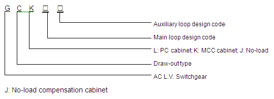
GCK Type L.V. Draw-out Switchgear Cabinet
GCK Type L.V. Draw-out Switchgear Cabinet satisfies the requirements of standards of GB7251.1, JB/T9661 and IEC439-1, compatible to the power system of 380-660V, 3-phase AC 50-60Hz, used for no-load compensation and distribution and electromotor controlling, indoor use. By user’s requirement, it can be designed as a compositive system as draw-out type and fixed type.
◆ The ambient temperature should be not higher than +40℃, not lower than -5℃. The average temperature during 24 hours should be not higher than +35℃;
◆ Latitude should not be over 2000m;
◆ The relative humidity of ambient air should be not more than 50% when the highest temperature is +40℃. The relative high humidity is allowed in lower temperature. (For example, 90% when +20℃);
◆ Gradient between the equipment and vertical side should be no higher than 5°during installation;
◆ Cabinet should be installed at sites with no fierce shaking and impacts, and at places to avoid electric component from erodent.
◆ Users may negotiate with the manufacturer when special requirements.
Basic technical parameter
|
Main Loop Rated Voltage (V)
|
AC 380, 660
|
|
|
Auxiliary Loop Rated Voltage (V)
|
AC 220, 380; DC 110, 220
|
|
|
Rated frequency (Hz)
|
50(60)
|
|
|
Rated Insulated Voltage (V)
|
660(1000)
|
|
|
Rated Current of Horizontal Bus (A)
|
≤5000
|
|
|
Rated Current of Vertical Bus (A)
|
630, 1000
|
|
|
Short Time Withstanding Current of Horizontal Bus (kA/Is)
|
50, 80, 100
|
|
|
Peak Value Withstanding Current of Vertical Bus (kA/O. Is)
|
105, 176, 220
|
|
|
Frequency Withstand Voltage (V/min)
|
Main Loop
|
2500
|
|
Branch Loop
|
1760
|
|
|
Bus Bar
|
3-phase, 4-line
|
A, B, C, PEN
|
|
3-phase, 5-line
|
A, B, C, N, PE
|
|
|
Main Loop Plug-in (A)
|
250, 400
|
|
|
Controlling Circuit Plug-in (A)
|
10, 20
|
|
|
Protection Degree
|
IP30, IP40
|
|
Auxiliary loop design
GCK auxiliary loop consists of two parts of AC part and DC part.
Auxiliary loop design of DC operation part is for electrical system in L.V. transformer substation of power plant or power generation sets, working power cable input design, general controlling designs of power supply feed-in cable or electromotor feed-in cable. The auxiliary loop design of AC operation part is mainly adopted for the L.V. system of transformer substation in factories and high buildings. By main loop design, auxiliary loop design is divided into 3 kinds of operation controlling functional units designs as auxiliary power supply cable input design, feed-in cable (PC) design and electromotor feed-in cable (MCC) design.
Option of electric components
To satisfy the requirements of high performance equipments, key components in cabinet are domestic advanced products with high disconnecting capability, and products based on imported technology. For example, breaker we select series F of DW15, ME, AH, DZ20, M, ABB; contactor we select CJ20, 3TB, LC1 etc; heat relay we choose JR16, 3UA, LRI-D.
These components are with high technical performance, compact structure, low weight, short arc or no arc. And it is able to satisfy the requirements of the equipment.
Structure features
1.1 Framework is composed with profiled bar which patterned CF28-1, CF28-2 from German AEG Company, corner connector and corner connecting board. Profiled bar is made of cool rolling steel by once bending and occluding, with installing holes of modulus as 20mm. By high precision of the installation dimension, the framework can be assembled flexibly and conveniently with few accessories but is very firm and durable.
1.2 Drawer, door and key components are made with mould. The frame and door is lacquered or electrostatic sprayed. Drawer and other components are galvanized and purified. So the cabinet body and drawer have good figure and can be substituted mutually, with a small contact resistor.
1.3 Cabinet body is metal-sealed type.
1.4 The capacity of capacitor cabinet accords to form 3.
Remark: If a main cabinet and two auxiliary cabinets in an order, an “A” is added behind the first auxiliary cabinet. For example, total capacity of 3 cabinets of GCJ-1, GCJ-2A, GCJ-2 is 120kvar*3=360kvar.
1.5 The dimension, type of drawer and key electric components accord to form 4.
1.6 Mechanical and electrical interlock is installed between drawer and cabinet door. 3 apparent indication of connecting, testing and separating position and localization structure on the drawer are in cabinet body.
1.7 Vertical bus is sealed in the vertical bus booth. When the drawer is drawn out, auto-covering slide block will drop down to block off the electriferous vertical bus booth from the drawer booth.
1.8 Considering the generalization and security of using dry-type transformer, economy of oil immersed transformer, the equipment can be grouped conveniently not only with dry-type transformer, but also with L.V. bus of oil immersed transformer.
2 Cabinet Structure
2.1 PC Cabinet
GCL1-4 general input cabinet, GCL5-7 general connecting cabinet, GCL8-9 big capacity feed-in loop. 2 loops downwards of 1600A are equipped in each cabinet.
2.2 MCC cabinet
84 types differed by width and depth of cabinet and different connection of auxiliary loop are in form 5 as follows. The “auto” in the form means that the connection and separation of auxiliary loop are completed during the in and out process of the drawer. The “manual” means that to insert or to draw out the plug of the auxiliary loop by hand complete the connection and separation of the auxiliary loop.
Four types of drawers in MCC cabinet are those with heights separately of 200, 300, 400 and 600, and with fixed board of 900 and 1800. 9 drawers of 200mm can be equipped in the MCC cabinet.
2.3 Capacitor non-power compensation cabinet
3 Bus System
3.1 Horizontal Bus
Horizontal bus (L1, L2, L3 and N)is equipped at the inner top of cabinet. Rating currents of horizontal bus are 630A (cooper bus of 5*50), 1600A (2 cooper buses of 10*40), 3200A (2 cooper buses of 10*100), 4000A (3 cooper buses of 10*100). Rating current of N line is 50% of horizontal bus.
3.2 Vertical Bus
Vertical bus is cooper bus of 630A (5*50) and 1000A (10*40).
3.3 Protection Earthing Bus (PE line)
PE line is installed at the lower part of cabinet. PE line and N line can be combined as PEN line as neutral direct earthing system.
3.4 Small Bus
Small bus can be installed by user’s requirement, with cabinet depth of 800mm.
4 Optional Principle
4.1 With rating current upwards of 4000A
4.2 When rating current of PC cabinet is upwards of 3200A and equipped beside MCC cabinet, MCC cabinets with depth of 600mm or 800mm are optional, while 800mm-depth cabinet is recommended.
4.3 When CT5 and CT6 are used, drawer must be pairs. Types of cabinets are GCL-8, GCL-9, with the depth of 1000mm, beside the PC cabinet.
4.4 GCJ-1-8 will in Form 3 must be adopted as capacitor cabinet.
4.5 The depth of MCC cabinet must be 800mm when a small busbar is installed to horizontal bus. And 5-10 cooper poles with diameter of 6mm can be installed in horizontal bus booth. (10 pcs downwards of 3200A are suitable, while 5 pcs downwards of 4000A are suitable.)
4.6 When installed by rows, MCC cabinets must be same sized and of same type.
4.7 At most 2 plug sockets of 10 lines can be installed to auto-plug drawer by controlling loop.
4.8 Due to figure difference between operating handles and auto switches, they can’t be installed in the same cabinet when QSA series.
Dimension and Groundwork
The figure dimension and groundwork refer to following drawing. Slot steel and bolts should be provided by users themselves. Connecting main bus, the surface should be leveled off to connect fixed if it is not plain caused by transportation and maintenance.
Dimension and Groundwork
The following materials should be provided:
1 Plain disposal drawing of distribution booth and ranging drawing of switchgear cabinet.
2 Main circuit single cable system drawing and main bus spec.
3 Theory drawing of auxiliary loop.
4 Types, specs and amounts of electric components in the cabinet.
5 Cabinet color and protection grade of cabinet shell (IP30 or IP40).
6 Thickness between bus slot and cabinet body (not includes the thickness of door), or the shell.
7 Special requirements which are not suitable to guarantee the normal use of other products.
【 Return 】
Copyright: ServiceTel: ICP: Link